
About VHS Engineering
VHS Engineering delivers reliable structural engineering solutions with a strong focus on quality, coordination, and project outcomes.
What Goes Into a Complete Steel Shop Drawing Package?
Practical insights from VHS Engineering on structural design, BIM, and project delivery.
10 Sep
What Goes Into a Complete Steel Shop Drawing Package?
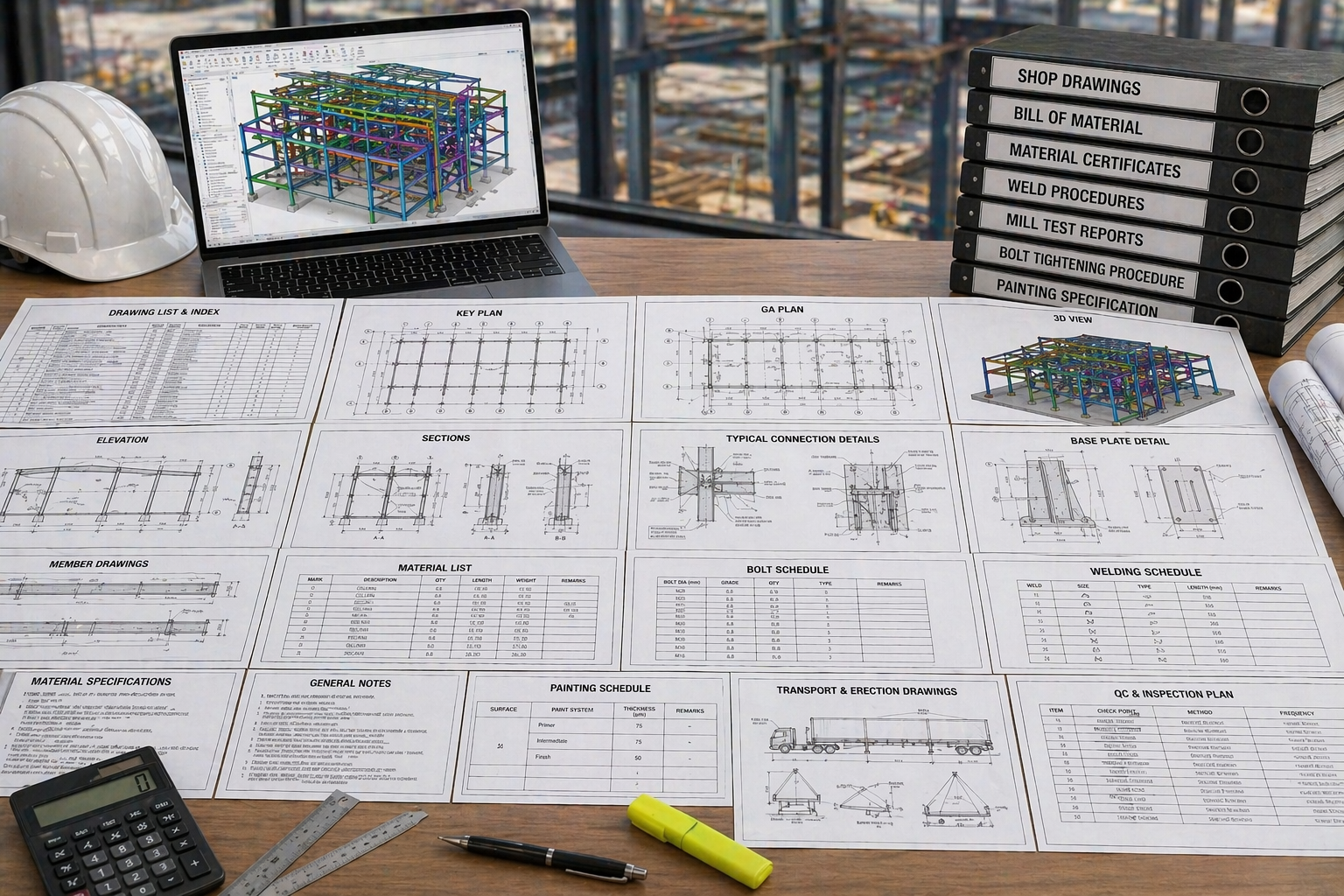
A steel shop drawing package is the full set of documents that a steel fabricator requires to manufacture, mark, and deliver structural steel members to site. It is not a single drawing  it is a coordinated set of documents that covers every steel component in the project, from primary structural members to the smallest connection plate and anchorage detail.
The quality of the shop drawing package directly determines how efficiently the workshop operates, how accurately members are fabricated, and how smoothly erection proceeds on site. An incomplete or ambiguous package generates RFIs, delays fabrication, and creates risk at the erection stage.
1. General Arrangement (GA) Drawings
General arrangement drawings show the overall structural layout  grid lines, column positions, beam orientations, and floor or roof levels. They establish the spatial framework within which individual shop drawings are interpreted. Every GA drawing must carry current revision status, a North point, and sufficient gridline annotation to allow fabricators to orient their work correctly within the project.
2. Member Assembly Drawings
Member assembly drawings  often called shop drawings or fabrication drawings  show individual steel members in detail: overall length, cross-section, hole patterns, cope details, weld preparations, plate attachments, and part marks. Each member has a unique mark that links it to the Bill of Materials and to the erection drawings that show where it is installed.
A quality member assembly drawing leaves no ambiguity: every dimension is given, every weld is specified, every bolt hole is located, and every finish or surface treatment is noted.
--- VHS Engineering Team"A complete shop drawing package is the fabricator's instruction manual. Every page must be clear enough that no one on the workshop floor has to guess."
3. Connection Details
Connection detail drawings show how members are joined  shear tab connections, end plate connections, moment connections, gusset plate bracing connections, and base plate details. They specify bolt grades, bolt diameters, weld sizes, throat thicknesses, and welding processes. Connection details must be consistent with the structural engineer's approved connection calculations.
Incomplete connection details are the single most common cause of RFIs during steel fabrication. At VHS Engineering, every connection in the package is detailed to a standard that fabricators can work from without seeking further information.
4. Erection Drawings
Erection drawings show how the fabricated members are assembled on site  member orientations, splice locations, erection sequences, and temporary support requirements. They are used by the steel erector to plan crane picks, set out columns, and install beams and bracing in the correct order and orientation. Erection drawings must be coordinated with the member assembly drawings: every part mark on the erection drawing must correspond to a unique member in the shop drawing package.
5. Bill of Materials (BOM)
The BOM  sometimes called the Material Take-Off (MTO)  lists every steel member and plate in the project, with quantity, profile, grade, length, finish, and weight. It is used by the fabricator for material procurement, workshop scheduling, and delivery planning. An accurate BOM generated from the 3D model ensures that the fabricator orders the correct quantities and that procurement aligns with the fabrication and erection schedule.
6. Anchor Bolt Plans
Anchor bolt plans show the location, projection, diameter, grade, and setting details for the holding-down bolts that connect steel columns to concrete foundations. These drawings must be issued to the civil or concrete contractor before the foundations are cast  getting anchor bolt positions wrong is one of the most expensive errors in steel construction.